Mastodon

We're looking for the trash fence...

Lots of stuff on the masthead

Posted on Thu 10 December 2009 in Navigation

I plan to put a Maretron NMEA 2000 weather station on my masthead and replace my incandescent bulb nav lights with this ORCA Green Machine LED navanchor light. Everything seems great but now I’m thinking how am I going to get these two on the masthead and not have them interfere with each other.

OGM-LED-Mount

The OGM is 2.7” in diameter and 2.7” tall.

WSO100-Mount

The Maretron WSO100 is 4.25” in diameter and 3.45” tall.

Ideally you could stack them, but I’m not sure how you’d route the wire around or thru so it didn't interfere with the functionality of the weather station or the visibility of the light.

I’m sure someone else has done this, another research project…


Evolution of a Porthole

Posted on Wed 09 December 2009 in Projects

Before

Porthole Water Damage

Demolition

DSC_7121

Almost Done

image

This is actually a shot of the dry-fit, but they look the same. The headliner is still down and the white you see around the portholes is just the primer. We do plan to paint them white though along with the headliner.


Next set of things in the refit

Posted on Thu 19 November 2009 in Projects

The boat has been moved form sitting in the yard where the bottom was prepped and painted, some keel damaged was repaired (oopsy), the v-berth was prepped by me, and the windlass was removed. The boat is now sitting inside the prep tent. I’ve not been to it yet, but I’ll go tomorrow and take a bunch of pictures.

from gave me a call about some blisters he saw along the waterline. We’re not sure if it’s just a paint issue or if there is some gelcoat damage. We’ll know more when they start to prep for painting. This is one of those “known unknowns” which could be nothing or could be expensive. We’ll find out soon enough.

The yard is prepping the boat for repainting the stripes, and I aguess polishing the hull as well as a bunch of fiberglass projects including closing up some thru-hulls, reinforcing the v-berth and moving the windlass. I also have a lot of chores to do:

  • Grind off a thru-hull so it can be pushed in and then glassed closed.
  • Remove the teak trim from the deck where the windlass was removed.
  • Cleanup the water jacket in the VDrive and sand off the corrosion on the input shaft.
  • I have a lot of measuring to do to determine the wire lengths needed for the new electronics and mast lights. I’ll start with just the lengths needed for the masts plus some extra so I can put in terminal blocks or connectors which will allow the masts to be pulled without cutting any wires.
  • I also want to work on replacing the hoses below the waterline. I’ll pull the hoses, measure them and pickup new hose from Fisheries or West Marine.
  • Dawn is probably going to star on the portholes or at least getting all of the pieces in place to make it happen.

Very busy weekend!!


The Refit begins !

Posted on Fri 13 November 2009 in Projects

If you follow @DeepPlaya on twitter you know a lot of this stuff, but for those of you who only read the blog here’s the full scoop.

Wednesday afternoon we moved Deep Playa over to A dock where <The Yard> uses the fixed mount haul out cranes (you could pull your dinghy this way) to remove masts. Because the cranes are fixed height you have to time all of this with the right tide to allow them to lift or lower your masts successfully. We got there right on time which in boatyard time means we were early. We milled around then docked and went to work. Basics steps to de-rigging your boat are as follows:

  1. Remove all of your sails and running rigging
  2. Unhook all of your mast lead wiring. This may require cutting some wires, you can add a terminal strip afterwards.\ You might want to lift the mast and see if there any connectors within the mast instead of cutting directly.
  3. Remove any boots around the mast if it is keel stepped
  4. Attach crane to the mast and snug it slightly so it will keep anything from falling over
  5. Pull all the cotter pins from the rig and loosen all the turnbuckles. Depending on your rig some can be removed before others.
  6. Snug the crane
  7. Completely [remove] disconnect all the standing rigging (Thanks Tom for the clarification)
  8. Lift the mast off of it’s step, being careful to lead all the wires cleanly out.
  9. Put the masts on a cart and take them to the yard or lower and fasten them on deck.

So, that’s the ideal way to do things assuming everything goes perfectly. I did not remove my wiring before I got there so I had to quickly do that. I ended up cutting the thick data wire to the RADAR (which I plan to upgrade) only to learn there was a connecter under the mizzenmast. The main could not be picked form its maststep. The aluminum mast was fused to the steel step, horrible combination of metals.

Because they couldn’t get the main out and it was dark we had to wait to finish pulling the rig until the following morning. They managed to get the mast out by grinding off the bolt heads holding the main maststep to the boat, then the pulled the whole mast, step and all up a few feet and knocked the step off the mast with a hammer. With the step removed the whole thing slide right out.

Now that the rig is down the boat was hauled and setup on jacks in the yard.

I spent the remainder of the day removing hardware from the masts. This went much better than the booms. There was a lot more hardware that easily unscrewed. I still have quite a bit left to do, but it feels good to be making progress rather than waiting to start.

You can see more pics of the refit as it goes along in our 2009 Refit set on Flickr.


Let the Refit Begin

Posted on Mon 14 September 2009 in Interior

I’ve been working on a document describing the refit we plan to do on Deep Playa. I thought it would be good to share it with all of you and see if anyone has feedback but also so others might benefit from seeing what I’m doing.

Here’s the first half of the document, still lots of specifics to figure out, but a good start.

Overview

This refit plan for Deep Playa includes replacing the standing rigging, re-bedding and improving the deck hardware, replacing and improving the running rigging, and new bottom paint and hull polishing.

This section will cover the highlights of the projects by area (Rig, Hull, etc) but the meat of the document with all the details will cover the projects in the phases they will be carried out.

This document will be reviewed with several yards and riggers for additional input and to help select who will do the work.

We like to do our own work where it makes sense (saves us money, teaches us key maintenance or survival skills) but there are times where specific expertise or time consuming work makes more sense to be done by a professional . To what degree we do things ourselves is to be determined.

Standing Rigging

The wire rope standing rigging appears to be original and it is overdue to be replaced. Replacing it involves dropping both masts, replacing all of the wire rope, inspecting an possibly replacing the chain plates, inspecting and possibly refinishing the spars, having new wire rope rigging made and then re-rigging the boat. At the same time any electrical, communications or running rigging projects that affect the standing rigging and the spars need to be done as well.

Planned Upgrades

  • Adding a isolators to the main backstay for the SSB antenna
  • Conduit for in-mast wiring
  • Strong Track
  • Running Rigging Related
  • Route all halyards internally
  • Add Spinnaker and Mizzen staysail halyards
  • Rope clutches for main, mizzen, jib spinnaker and mizzen staysail halyards
  • Inspect sheaves and probably replace, internal routing probably changes them all together
  • Spreader Boots
  • Electronics & Communications

Main

  • Masthead NMEA 2000 weather station
  • Masthead VHF Antenna
  • Masthead LED Anchor and Nav Lights
  • Masthead Davis Windex
  • Spreader LED lights
  • Foredeck Light
  • Hailer Mount
  • Ensure the crane has all that is necessary for planned sails
  • Spinnaker halyard

Mizzen

  • Masthead NMEA 2000 GPS
  • Masthead AIS (backup VHF) Antenna
  • Spreader LED lights
  • Foreword Light
  • Self leveling Radar Mount
  • Ensure the crane has all that is necessary for planned sails
  • Mizzen staysail halyard

Open Issues

  • Refinishing the spars – What’s the cost
  • How many things that are bolted to the spars need replacing?
  • Main and Mizzen reefing are a mess
  • Rigger needs to be identified
  • Rigging Inspection Needed

Running Rigging

All of the lines for the running rigging except for the Jib Halyard and the Mizzen Sheet are in a very sad state and need to be replaced. In addition to that there are several very flawed installations such as the main sheet winch and main traveler which are also functioning poorly. At this point based on pricing and helpfulness I am plan to use Garhauer almost exclusively.

Planned Upgrades

  • Move main sheet winch inboard
  • Replace main traveler
  • Add rigid boom vang
  • Increase main sheet purchase

Open Issues

  • Can I get a bulk discount from Garhauer?
  • Should we do this before we make decisions on our sail maker?

Deck Hardware

Beyond the rigging fittings which will be pulled and rebedded all other deck mounted hardware will be rebedded as part of this the lifelines will be moved to the toe rail as well.

Planned Upgrades

  • New Garhauer toe rail mounts for life lines
  • New lifelines and fittings
  • Bow trim piece is broken and needs to be replaced
  • Moving the windlass foreword and the hawse pipe out of the berth
  • Add additional bow roller

Open Issues

  • Will we use wire rope or line for the lifelines?
  • Should we add any fittings for jack lines?
  • Can we afford new stern pulpits placed on the toe rail? Would include:
  • Bimini
  • Solar Panel mounts
  • Stern reel mount
  • Close the Bow Tank Hole?
  • Will a horizontal windlass be needed
  • Can the existing windlass handle two anchors
  • Will the toe rail track need to be shortened to accommodate the lifeline changes

Hull Work

The main two parts of this project are new bottom paint and polishing the gel coat. In addition to that we want to evaluate all the thru-hulls and see if any might be eliminated as well as make modifications to our ground tackle management.

Planned Upgrades

  • Remove unused thru hulls
  • Toilet overboar
  • Toilet intake
  • Stainless steel on the bow to protect hull from anchors
  • Bow padeye for anchor snubber
  • Rebed and inspect starboard hatch
  • Combine knot meter and transducer
  • Inspect cutlass bearing and plan to replace
  • Upgrade transducer to one with temperature, maybe not a thru-hull; maybe add or instead use fish finder type.

Open Issues

  • Do we “plug” or glass closed unused thru-hulls?
  • Should we close off the galley sink intake?
  • Is the crazing in the gel coat around the hull a problem or just an age issue? Will polishing clean it up? Should we even care?
  • What Hull paint should we use? Need to look at the PS articles and compare NW to CA paint results

Headliner, Portholes and Hatches

Removing the headliner is a necessity todo all the other work; we plan tO replace it at the same time as well. The damaged teak along the cabin top will be covered so it blends with the new white headliner as well to create a visual lift to the salon. The leaky and sealed closed portholes will also be replaced with the New Found Metals portholes we acquired this summer. The hatches are also questionable (the aluminum is brittle in places) and leaky they will be replaces as well while the headliner is out. In the final installation the teak colored strips holding up the headliner will be painted white to blend them with the headliner.

Planned Upgrades

  • New Found Metals Portholes
  • Replace hatches
  • New headliner
  • New cabin top wood (cover up teak)

Open Issues

  • Brand of hatches TBD, New Found Metals is supposed to be making hatches this fall
  • Headliner material is TBD, Originally wainscoting was the plan, are we really over that?

Lots of things accomplished

Posted on Sun 02 August 2009 in Projects

We’re planning to head to Poulsbo next week for the Lats N Atts party and then to the San Juans, all in all it will be about 10 days on the water, but before we could do that I wanted to check a bunch of things off the list, here’s a running checklist:

  • New outboard bracket
  • Check-valve in the bilge line\ The bilge worked fine, but an extra 2 or 3 of inches of water would run back out of the hose after the pump quick running. I put a check-valve in the line and now their is minimal water in the bilge.
  • Completed rewiring the anchor washdown pump\ When I pulled the sink from the v-berth, there was also an anchor washdown pump using that through hull. I pulled the wiring back then and had never gotten around to wiring it back up. I finished that this weekend. Because I’m an idiot it required extra assistance from the gang at Cruiser’s Forum, I’ll let you read that story on their site.
  • Cleaned the anchor locker\ Really this is just the storage area for the winch handle for the windlass, rubber “mud” gloves, and the anchor washdown hose.
  • Cut some chain\ I had a 100’ length of 5/16” chain that I cut into two 50’ lengths to use with my two backup fortress anchors or to add to my main rode if needed. For my stern anchor we will use a fortress, 50’ of chain and 400’ of dynemma webbing on a reel from Quickline. Cutting it was pretty easy, I pulled it taunt by cleating it off between two cleats on the dock and cut it with a hack saw.
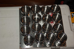
  • Spice Rack\ DSC_5205Dawn has been wanting a spice rack. She picked out a magnetic system from Storables. The magnets are really strong. I gave it some good shakes and they are not going to fly off. The might slowly work their way down, but we can easily put a stopper board along the bottom if needed.
  • !! Drank Beer !!

Whew… that’s a lot of stuff, better rest up before we head off; can’t wait to leave the dock!!!!


Installing the Composting Head

Posted on Wed 08 July 2009 in Interior

DSC_0009

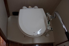
When we bought the boat it had a normal pumping toilet which went to a Y valve for pumping into a a smallish holding bag or through a macerator pump and out to sea. This was an OK setup for blue water sailing and Coastal Sailing in Canada where pump outs are few and far between and holding tanks are not required. We didn’t like this setup for our Puget Sound home waters nor did we like it for when we’re out cruising. Instead we’ve decided to go with a Nature’s Head Composting Toilet. I’ve blogged about that a few time before, but this post will describe the process from beginning to end.
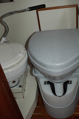
DSC_0013\

Here is a side by comparison of the two seats to verify the height of the new toilet will be about the same as the old. Notice that the old toilet is sitting on a little platform. Also that the handle is bent (oops).
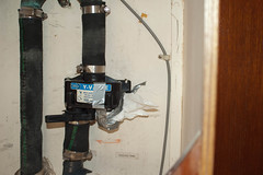
DSC_0213

The first step was to rip out the old toilet, plumbing, holding bag, macerator pump, and close up the through hull. The raw water in came off the drain for the sink in the head so that was fine, but the macerator pump through hull was dedicated and we closed and put a cap on that through hull with only a minor scare as the through hull didn’t really close all the way anymore.

This picture is of the valve which allowed you to pump the holding bag out through the macerator pump. All of these hoses smelled horrible and would have needed to be completely replaced. These hoses are also in a hanging locker which today I’m happy to reports smells like a new house. ;-)
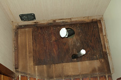
DSC_0226

Next we ripped out the old toilet. In this pic you see we have removed the toilet and the little platform on which it sat. The floor here was damp, but not water logged. I ran a heater in here for a few days and it dried out nicely. You can see the plywood subflooring and the teak and holy sole here. We had to bring this all up to level so we put in a 1/2” sheet of plywood (it may have been 3/4” I forget) which was glued in place with Gorilla Glue and screwed down to the sub-flooring. This gave us a level, hmmm ok let’s call it a flatter surface to work with when we went to lay in our tile.
2008-11-18 22:36:21 -0800

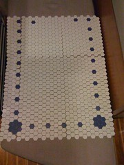
Dawn is the detailed oriented one in our house and but that I mean she does all the detailed design work and finish work when we work on projects together which is usually always. I also operate any heavy machine and anything that beeps when you back it. In this case Dawn came up with the pattern of the tile design, I laid it out and rough tiled it in. Dawn then came in and caulked it, did the final grouting and sealed it.
DSC_3073

Next I had to cut the hole and install the vent hose for venting the composting chamber. This was a bit nerve wracking for me because cutting a hole in your boat sounds like a pretty dumb idea to me, but here we go.

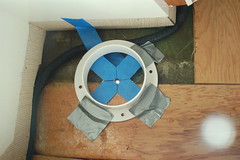
This first shot is how I lined up the hole from inside the head. I had a pretty open area on deck, but the placement from below was more crucial because of the wiring that needs to snake around the vent. The vent is a standard Vetus 3” Mushroom vent. I used one of the finishing trims from the vent and some tape to line it all up. I then drilled a hole in the very center of where I wanted to cut the larger 3” hole. You can see how I lined it all up and the initial center-hole drilled through the cabin top. Notice that half the hole goes through the deck and half also has a some additional wood for holding up the headliner. We’ll need to have the whole are flush for mounting the vent.
DSC_3075

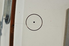
This is a shot from the top side where I have already started drilling through with the 3” hole saw bit. If you’re not familiar with these bits, they have a drill bit in the center and a circular ring of teeth to the size of the hole you want to cut.
DSC_3077

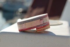
This is the plug that was cut out when afterwards. Notice my balsa core is very clean and DRY. That’s a very good thing!

I also think it looks kind of cool and it showed me how my boat was put together.

DSC_3247

I mentioned before that we’d need to have the are flush for mounting the vent, so I epoxied up some 1/4” plywood and here you can see that being held in with clamps while it dries. I was doing this in the winter so I put a plastic container over the outside and taped plastic down over that so no water would get on my epoxy work.

At the same time this was being attached, I also put epoxy along the inside edge of the hole I cut. This seals the balsa core from water getting into it.
DSC_3275

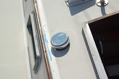
Here’s a shot of the finished vent installation. Shiny. shiny.

The white trim piece you saw a few pics back slides into the hole from underneath and into the bottom of the mushroom vent. The mushroom vent sits flush on the deck. I put some 5200 along the bottom of it and set it into place. The both sides screw into the cabin top separately. There is no clamping load on the deck at this point.
DSC_3178

DSC_3177

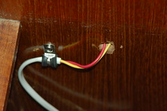
Next I needed to run a wire to the bulkhead behind the toilet to power the computer fan that draws air through the composting chamber. I wired this into its own switch on my breaker panel and put in a two prong DC plug on the wall behind the toilet. I could have hard wired this, but I think the plug is a nice finishing touch and if I wanted I could use that plug for something else.

The first shot shows the wire behind the plug, its in a small locker and then the plug itself. I used Ancor marine grade tinned wire and a Sea-Dog polarized 12volt outlet (PN SDL 426142-1). It was important that the fan be wired correctly, because it wouldn’t just run the wrong direction it would burn out the fan. That’s why I went with the polarized plug.

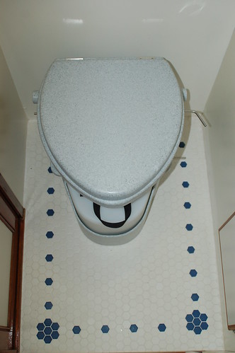
The toilet mounts to the floor with two brackets and then screws into the brackets with handles so i can be removed for emptying. I through bolted the brackets all what through about 2” of sub-flooring with bit washers. That toilet isn’t going anywhere.

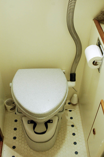
Here are two shots of the almost finished (left) and finished project (right) with the vent hose and new toilet paper holder which Dawn installed. I include both pics because I got the exposure off on the 2nd shot and the tile doesn’t look at nice.
DSC_2235 _DSC3905

The project was pretty easy even for a newbie like myself. We’ve been using it for several months and have emptied the compost chamber once. It smelled like dirt to me, a complete non-issue. Just like we intended. Having extra urine chambers is a definite must-have as when there are 4 people on board and you’re partying (like on the 4th of July) you’re going to emptying them frequently.

I have a lot more pictures related to this project on the Flickr tagged as Systems: Composting Toilet.

Here are our operating instructions:

  1. Lift Seat
  2. Sit Down (yes, even if you’re a guy and you’re just going pee)
  3. If you just have to do number one, go for it. It’s ideal if you can keep your aim towards the front of bowl so most of your business goes into the urine container.
  4. If you have to go #2, with your left hand flip the little lever which opens the trap door to the composting chamber. This is not a chamber into which you yourself would want to enter.
  5. Poop ! The trap door seems to be lined up perfectly for me, but remember “In the hole is better than on the bowl!” © (tm)
  6. Now your done your #1 and your #2
  7. Wipe – fold the paper over and set it aside. You are going to throw it away in the trash, not in the bowl.
  8. Put in one scoop of coir which is stored in the sliding cabinet.
  9. Close the trap door
  10. Squirt the bowl with the spray bottle just to wash down any urine in the bowl. 3 or 4 squirts is usually good.
  11. Turn the crank on the bottom right side (as you face the toilet). Turn it gently 3 or 4 times. If you go crazy with your turns you flip stuff up against the bottom of the top half of the toilet and it makes a mess when I go to empty it.

Plumbing Upgrade and Starter complete

Posted on Sun 07 June 2009 in Pearson 424

Raw Water Strainer

This weekend I finished installing the starter. Along the way I decided to replace the bonding wire on the starter to the v-drive with tinned wire because the existing wire was corroded. As I was doing this, I also decided to replace the bonding wire from the v-drive to the raw water strainer because it had broken a few months back. Removing the nut on the raw water strainer lead to the strainer breaking.  The strainer (bronze) was bolted to an aluminum bracket with stainless steel screws and it had started to bend at the hanger points. I was planning to replace this fall when I haul out, but turns out I needed to do it today. I put a board on that aluminum bracket and put in a new raw water strainer. All in all it was pretty simple, the new fittings lined up a bit differently, but the new strainer looks great and will provide years of reliable service! I have one more bonding wire to put in, just need a 8 AWG to number 10 screw ring terminal to check that one off the list.

DSC_4505

I also finished installing the starter this weekend after I painted it and let it dry. It pretty much popped right in, I fastened in all the bolts to the block, put the new bonding wires on and then hooked up the battery cables and starter switch. She started up on the first try and water ran well through the exhaust. Everything is look good!

Shower mixer and nozzle mount

Finally, I finished our plumbing upgrade as well by putting in a new shower mixer valve and handheld wall mount sprayer. The original faucet was a 4” on center individual knobs for hot and cold and had a fitting for the shower nozzle right on the faucet. When I pulled this off the wall I was left with two holes in the whole. I put a Shurflo mixer volume control in the bottom hole and a wall mount for the shower nozzle in the top hole. This completes a project I started last summer!


Engine sound proofing

Posted on Sat 23 May 2009 in Interior

DSC_4132

Today I got most of the new sound insulation installed on the engine cover. The old soundproofing was flaking and falling off the boards to which it was attached. The new material is a vinyl foam insulation with a silver Mylar finish from Sound Tec NW. The material is about 2" inches thick with two layers of foam sandwiching a rubber sound and vibration barrier material that is 2 pounds per square foot.

Installation was pretty simple. I took the surround to the workshop (more on that later) and made cardboard templates of each side and the lid. Next I traced teh templates onto the material which I cut using a SHARP drywall razor blade held in my hand with a duct taped finger so I could push really hard. This was pretty easy but I have pretty resilient hands. I think someone else might want to find a better way to cut it. Anyway, for me not a problem. The reason the blade was not in a knife was I need to use the full 2” length of the blade.

Next I dry fit everything together in the shop made a few tweaks and then took it to the boat. Once on the boat again I dry fit everything to make sure it all fit. That out of the way I used spray adhesive putting two coats on the wood and the foam before mating the two together. You need to be really carefully when you do that because the glue is very sticky and separating the two would have been very hard if not impossible with out damaging the foam.

Once the glue setup, which was pretty much instantaneously, I took #9 2-1/2” screws and matching fender washers and attached the foam to the wood. Before placing the screws in the foam I drilled them into a candle to wax the screws. This was a tip from Dave the Sound Tec NW guy. This kept the screws from gripping the foam and tearing it. The screws and fender washers went in without a hitch and I put them in just enough to quilt the Mylar and not so much that I went through the boards.

As you can see from the picture above the material looks great and I can’t wait to fire up the engine. There’s one additional picture on Flickr as well where you can see the individual layers of material. You’ll notice in that picture that only 2 of the three sides are installed. That third side would be impinged upon by the hydraulic prop-brake on my engine (right where the dark spot is) so I either need to remove that brake (which I plan to do eventually) or I need to cut out a window in the insulation so the brake has the room it needs. I also need to finish off the edges with the matching 2” Mylar tape, but that it what we call “detail work” and Dawn is better at that than I am.

Dave from Sound Tec NW was very helpful and easy to work with, I would definitely recommend talking to him if you’re looking to do a similar project. I bought a full sheet of the material and the tape for just under \$200.


Instrumentation and Electronics

Posted on Tue 21 April 2009 in Geek

I have some older electronics on the boat which draw a lot power, have horrible or no displays and I'm geek I have to have the new newness. Here's a brief overview I wrote while I was eating lunch to get some of my thoughts written down so my mind would stop racing. As a general rule, I've come to view the overall system in two main sections.

The general purpose NMEA 2000 bus for gathering a displaying information via multi-purpose and multi-vendor displays and data sending units. E.g.: weather, dc usage, wind, location, etc.. These components all should interop with the exception that they need their vendor specific display for configuration. These items feed into the Navigational Components as well as other systems like the DSC on the VHF and to the PC for other applications as well like SSB position and weather reports.  For the General Purpose instrumentation I plan to use Maretron components and one DSM 250 (color) display in the nav station for configuration of those devices. We will also have one or two multi-function displays in the cockpit. I'm not yet sure what brand or model. I would include engine sensors in this category but I have no plans to wire up my 1981 Weterbeke 58 (probably can't) and I'm not currently planning on doing a repower. The sending units will include:

  • GPS100 GPS (1)
  • WSO-100 Wind and Weather (1)
  • SSC200 Compass (1)
  • DCM1000 DC Monitor for each battery bank and Solar Panels (3)
  • USB1000 USB Gateway to connect to PC (1)
  • DSM 250 color display (1)
  • TLM100 Tank Level Monitors for both fresh water tanks and the diesel tank (3)
  • NMEA 0183 Adapter for connecting VHF to Network (1) (maybe the GPS can do this automagically)

Beyond the general purpose systems, the Navigational components (RADAR, Chart plotter, PC Nav Software and Autopilot) must all be of the same brand and compatible in order to get ChartRadar overly on the plotter and the PC as well as single point control of the auto-pilot (i.e, the ability to change course from the PC Or the Chart plotter. To that end, I plan to go exclusively with Raymarine. I'm basing a lot of this on the survey results from the SSCA ( >50% of member surveyed use Raymarine) and hands-on experience at trade shows. I will be using the Navionics Gold cards for charts. I see no need to have the 'looks cool' 3D bathospheric views since they are based on such minimal data especially where we plan to Cruise (S. Pacific). I'm less resolved about what models on these items but the basic components will be:

  • Chartplotter - I'm guessing the C120 widescreen, but I need to dig into the differences. The E does not yet appear to be any better for my needs than the E.
  • RADAR - 24" HD radome model. Big decision here I think is 2kw24nm or 4kw48nm.
  • Autopilot - Need to think this through more. Not sure how this and the Capehorn windvane will interact yet. We might be able to use a tiller autopilot and the windvane quadrant... save some \$ and could afford to carry a full spare maybe... ??
  • Depth Sounder Fish Finder - This is just for geeky fun. I like the idea of being able to see contour information, not really for fishing. This integrates with the chartplotter and PC Software.
  • PC Software - Raytech RNS. Rosepoint Nav really has the best software, but I want a dedicated charplotter AND a PC and they have no solution for that.

Open Issues

Cabling

I think I'm settled on Maretron Mid size cable for the backbone and their smaller cable for all the drops to the sending units and non-Raymarine components. I’m guessing that I will run the main bus from starting at the spreaders on the main mast and ending at the spreaders on the mizzen mast. I think that will be far enough to let me run the lighter weight cables to the mastheads where needed. The run from the main will go throughundernear the nav station and then along the foreword end of the cockpit which before heading up the mizzen, again this will let me add displays and reach the batteries.

I'm not sure if I'll need a separate smaller bus for the Raymarine Seatalk HS network. I think I do since at a minimum the RADAR and chartplotter and PC don't talk over the NMEA 2000 bus.

AIS

We will add AIS closer to our departure time. I'm 99.9% sure I'll go with Raymarine again with the thought that it is all about the ability to overlay the information.

The next step is going to be to draw this up and start taking to sales reps here in Seattle looking for the best prices and service.

If you have any thoughts on my my overall plans feel free to chime in. I’m particularly interested if there are any known Raymarine Maretron interop issues.