Mastodon

We're looking for the trash fence...

Battery Heater - Facon Test

Posted on Mon 23 October 2023 in ADVVAN

Facon Heater Pad Wires

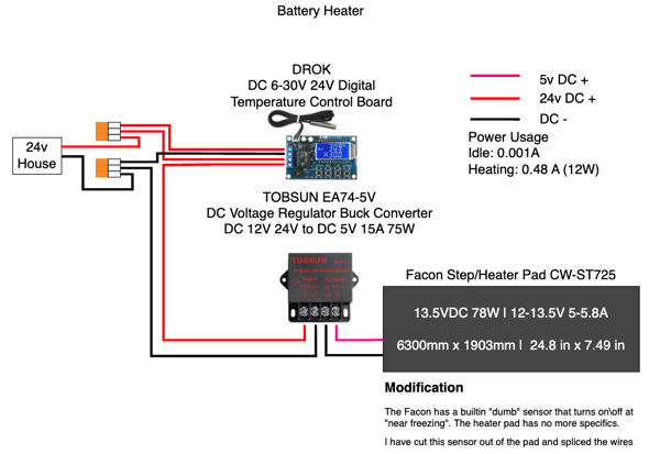
In the previous post I did some testing of a battery heater system and the pads were able to melt XPS foam. I was concerned about this and wanted to do some testing with pads from Facon which are used in the RV world for tank heaters.

The Facon pads are desinged to be used at 12V and draw about 4-6 amps depending on your voltage. They have a built in hard-wired temperature sensor that turns the pad on when it is "near freezing". There is not a specific temperature mentioned.

I wanted to test these pads at different voltages to see how hot they get. I would not plant to use them with their own temperature sensor but rather with the DROK temperature controller I used in the previous test.

Modification

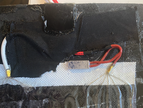
At first, I thought I had ordered pads without the thermostat they advertise because the it is just a pad with two wires coming out of it. I had assumed a thermostat would be am external device. I was wrong. The thermostat is built into the pads. It is inline with the positive wire, under the foam approximately 1 inch (2.5cm) from the heating wires. I believe as-is the heater would likely cycle on and off quite a bit as the thermostate is sensing the temperature of the pad and not the ambient air or the tank\battery it is heating.

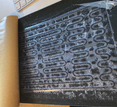
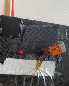
To modify the pads, I pealed back the glue, and the black tape covering up the positive and negative wires. I then cut the positive wire, removed the thermostat and used a wago connector to rejoin the wires. In this configuration I used my benchtop power supply to test the pads at various voltages.

Facon Heater Pad Wires Facon Heater Pad Wires

Test Results

Voltage Amps Temp (F) Range
25 8 Hot very quick
12 4.7 115-145 F
5 2 90-95F

At 5v, and in an enclosed space, I think these heater pads would be perfect for batteries. They are not going to melt anything and they will keep the batteries warm. You could argue they'd heat more slowly than at 12V but I think that is more of a benefit than a problem.


Battery Heater

Posted on Sat 14 October 2023 in ADVVAN

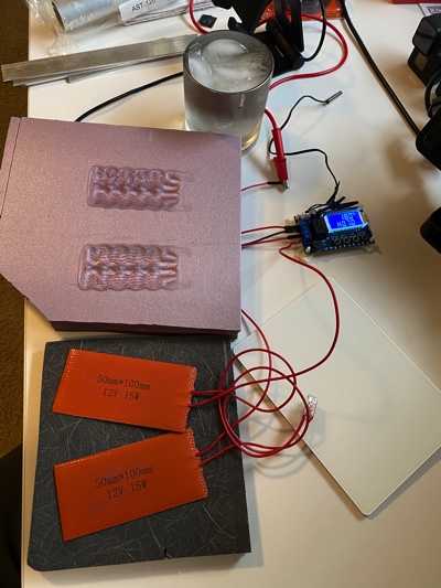
Battery Heater Test Setup

As the fall sets in and the winter is coming, I did some test of a battery heater system. The parts of this system are:

The DROK temperature control board is a nice little board with a temperature sensor that can be used to control the output. The temperature sensor is a thermistor that is attached to the board with a 2 pin connector. The board has a 3 pin connector for the output. The output can be configured to be on when the temperature is above or below the set point. The board only supports Celsius display and settings.

The heaters are 12V 15W silicone pads. They are 50mm x 100mm.

At 24.8 Volts

With the heating pads off the DROK draws 0.001A. The heating pads draw 1.377. The pads reach over 300F!!

At that temperature they are hot enoogh to melt XPS foam very quickly. They did not seem to have any effect on the Coosa board.

NOTE: I am considering these materials in my winter battery enclosure.

Comparisons at other voltages:

Volts DC DROK Only (A) Pads On (A) Pads Temp. (F)
24.8 0.001 1.377 300 (open air)
13.8 0.004 0.773 190 (covered 5 min)
12.0 0.006 0.690 220 (covered 25 min)

The 12V test was done with the pads covered with a piece of XPS foam for over 15 minutes. I was reading 200F max, but usually around 190F. At 25 minutes, I did checked again and it was 220 and had started to melt the XPS. I uncovered the pads and they cooled down to 190F rapidly. The room I was in was 71.2F.

I then set some 1 inch wide by 1/8" thick aluminum bar on the plates and let is sit for 10 minutes. The temperature of the bars was max 93F and as low as 77F in the end not under the pads.

Next test was to use the aluminum bar and set the XPS directly on the bars. 10 minutes in max temp was 122F and the pads were around 135F. The XPS was not melting.

I'm not decided exactly how I will go but I thought this was interesting and worth sharing. Some thoughts:

  • Definitely do not want to put the XPS directly on the pads. I'd even say not on the aluminum bars or other heat sink either to be safe.
  • Definitely want to run at lower voltage. I did test at 5V and the pads did not get warm at all so 12V it is.
  • A heatsink greatly reduces the max temperature of the pads even when covered with the XPS there was enough air movement to keep the pads from getting too hot and melting the XPS.

And here is the timing issue…

Posted on Mon 26 September 2011 in Systems - Electrical

I figured out why the ACR didn’t flip to combined in time… right out of the documentation:

Blue Sea Systems CL-Series BatteryLink ACR PN7600 Owner’s Manuual

Internal time delay prevents relay action for transient conditions, voltage must be within range for approximately one minute to cause closure, relay will open when overvoltage is detected for approximately 15 seconds.

The regulator definitely went from an acceptable charging voltage to an overvoltage situation in less than a minute.


Overcharging Problems

Posted on Mon 26 September 2011 in Systems - Electrical

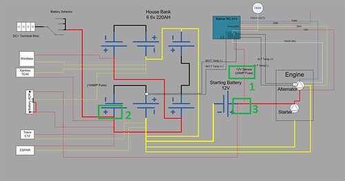
WiringDiagramExplanation

(CLICK GRAPHIC TO ENLARGE)

Not sure most of you will want to read this, but to my fellow boaters here goes…

When we had the engine out of the boat to replace the fuel tank we also decided to upgrade our alternator from a 65Amp model to a 100Amp model and to add a Balmar MC614 three-stage external regulator to increase our engine based charging capacity. We also made changes to our battery configuration. We combined all of our existing batteries into one 660Amp Hour (Ah) bank instead of two banks of 440Ah and 220Ah. We also added a single dedicated 12V starting battery.

Our starter is wired to the dedicated starting battery and the alternator charges this battery first. When there is charge being supplied to this battery our Blue Sea 7600 Automatic Charge Relay (ACR) combines the house and starting batteries so the alternator now charges all the batteries. In order for the Balmar external regulator to control the alternator output properly it monitors the voltage of the batteries it is charging (see 1 above). The problem we experienced was our starting battery was being overcharged so much it started to boil the water off. Here is what we think happened.

The two key components in this are where the 12V Sensor wire (1 in the drawing) is attached, 2 the house bank or 3 the starting battery and whether the ACR has the batteries combined or not.

Originally we (myself and our experts) believed the 12V sensor wire could go on either bank since we believed when the ACR saw a charge voltage it would combine the batteries, the regulator would then see the combined voltage of all the batteries and adjust the output of the alternator accordingly. We had the 12V sensor wire attached to the House Bank (2).

We still think that at some lever we’re correct in our assumption, however we now believe there is a race condition where the following happens:

  1. The Batteries are isolated because the house bank is not at full charge (Undervoltage on the ACR)
  2. The Engine starts and the regulator is responding to the low voltage on the sensor wire on the house bank (2). It then tells the alternator to  output more power
  3. The ACR can’t “see” the additional power from the alternator because the batteries are not combined so it tells the alternator to output MORE power.
  4. Now the ACR wakes up (or its sample frequency is less than the regulator) and it sees too much current on the Starting battery and now does not combine the batteries because there is an Overvoltage situation on the starting battery.

The basic problem was the ACR didn’t combine and the regulator was getting mixed signals by monitoring a bank that was not being charged, since the ACR did not combine, while simultaneously charging the hell out of our starting battery. We believe this is what was happening at sea. We know for sure we have reproduced this at the dock.

In order to eliminate this we moved the 12V sensor wire from the house bank to the starting battery. Now regardless of if the ACR combines the battery banks or not at least the regulator is monitoring the voltage of the battery is charging when the ACR has the two banks isolated.

We tested this today and we were not able to get the regulator into an overcharge state. We’re going to test a few more times over the next few days. We’re also going to contact Balmar on Monday and Monty at Englund Marine is going to contact Blue Sea Systems to confirm what we believed happened and that our fix is correct and also just to check to see if they already know something about this happening before.

Another day another thing learned…. ya gotta love it! (DISCLAIMER: We’d love it a lot more if it weren’t foggy and rainy)


Battery and Alternator Upgrade

Posted on Tue 20 September 2011 in Systems - Electrical

We’ve hinted at bits and pieces of this along the way, but I wanted to write up a more formal review of the changes we made this week while we had the engine out to replace the fuel tank.

Our original battery system was 2 banks of 4 and 2 6Volt batteries that were combined to make two banks of 220Amp Hours and 440 Amp Hours each. This was proving to be a bit limiting. I also suspect our batteries are waning and we’ll replace likely replace them further down the road. However, for now what we’ve done is create on large house bank combining all of these batteries into one 660 Amp Hour bank and we added a second 12V dedicated starting battery.

The new positive post of the new battery is wired directly to the starter and the negative joins the common negative bus in the house bank battery trays (i.e., they are wired together).

We already had a Blue Sea Automatic Charge Relay which combines both banks whenever it sees an adequate input charging current on either bank. For us this means that when the alternator is charging the starting battery it will combine and also charge the House, or when the solar and\or AC Shore Power Charger is charging it the  House it will also top-up the starting battery. This second possibility is called a dual sensing ACR and is somewhat less known about, read the Blue Sea Page on ACRs for more on that.

The battery changes should give us adequate power to not have to run engine for charging as frequently. However our alternator was only 65Amps and it had an internal single-stage regulator.

We upgraded our alternator to a 100amp Leece-Neville 8MR2401UA which was a physical drop-in replacement (same size, bolt pattern etc.) as our smaller 65Amp Leece-Neville. This was the maximum size we can run our engine with a single 1/2” belt.

We also replaced the internal regulator on the new alternator with a Balmar MC-614 three-stage or smart regulator.This regulator senses the voltage of the battery, temperature of the battery and the alternator and adjust the output of the alternator to provide the best charging current given the state of the batteries and the environment conditions.

The process seemed like it was going to be:

  1. remove the old alternator form the engine
  2. remove the internal regulator from the new alternator and install the conversion kit to allow the alternator to be controlled by the external regulator. There are excellent step-by-step instructions on that here.
  3. Bolt the new regulator onto the engine
  4. Wire the external regulator to the alternator, Ignition (or a pump driven solenoid which turns the regulator on and off) and its sensors to the battery bank (temperature and voltage) and alternator (temperature)
  5. Mount the external regulator

Seems pretty straight-forward and in fact all of that took a few hours. This is where easy goes crazy…. I was doing this over the weekend and all of the pre-tests Balmar says you should run using your voltmeter were not working properly. I spent at least a day tracing wires all over the engine compartment, under the cockpit floor and the lazarette to ensure I was wiring the thing correctly. But despite seeming to be wired correctly, in the end it wasn’t working right and the problem had to do with how much the new alternator and the old alternator differed from each other. The old alternator was case-grounded which means it was grounded through the way it was bolted to the engine. The new alternator was externally grounded which means you need to run a wire from the negative (-) post on the alternator back to the negative (-) on the batteries (our your common ground).

It took about an hour on the phone with Rich from Balmar and his patient troubleshooting guidance (and an emailed picture of my wiring) for him to come to the conclusion about my ground problem with the alternator. We borrowed a jumper cable from the always helpful Kyle Cox at Tarheel Aluminum Fabrication (he made our tank) and we tested our theory… BINGO! Everything was working yaay!!! Phone support, let me restate that. Knowledgeable, technical, skilled phone support is awesome thank you Balmar!

Now our alternator and regulator are working properly!


Trying to wrap things up

Posted on Mon 19 September 2011 in Fuel

We're still in Charleston. Still trying to get all systems back online. The main part of the project removing the engine and putting in a new fuel tank are completed. Friday we along with Kyle from Tarheel Aluminum Fabrication lowered the engine back through the companion and set it on its new mounts! Saturday we finished hooking up the engine, new 100amp alternator and external three-stage regulator. This morning we start the engine for the durst tine and it fired right up, but the regulator is not coming on, which means we can't charge the batteries without shore power. the engine is also running a little hot.

I spent most of today working on the regulator with the voltmeter checking how things were hooked up. I won't bore you wight the details on that, but I think it's a problem with the ground and a call to Balmar tomorrow should resolve that.

As for the engine temp, we need to make sure there's no air in the cooling system which seems pretty straightforward.

In addition to all that Dawn has also been working n some teak projects, stripping the cetol from the hand railings in the cabin top and she sanded down the campionway hatch boards and trim. It's going to look amazing when she's done!!!

We are definitely feeling the need to head south, but also seeing that the immediate weather patterns aren't looking great either. When the engine is 100% we'll start looking to pick our window to jump to SF or maybe another intermediary stop like Port Orchard or Eureka.


Still not done

Posted on Fri 19 August 2011 in Projects

When we were still on the dock at Shilshole we'd get asked all the time "when you going to be done?" And I'd always say, "never!" Well, in that spirit you should know that we're not done yet!

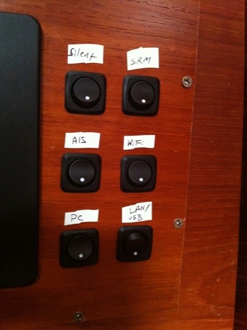
Today I worked on adding six new switches to control some functions of the AIS and power on/off various components of what we call the NavSystem. The new switches will allow us to turn off the transmit portion of our AIS to save power or avoid being tracked by CB. The other switches will allow us to turn off the PC, WiFi Bridge, LAN/USB Hub, and the NMEA 2000 network (instruments). All of these things used to come on or off all at once, now we can more granularly control our power usage, which us very good thing!!

20110818-105643.jpg


Dr. LED Under-Cabinet LED Light

Posted on Sun 30 January 2011 in Boat Shows

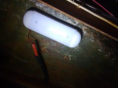
While at the Seattle Boat Show Dr. LED was showing some new under-cabinet LED lights. They have two models, one with white high & low and one with white & red LEDs. I bought one of the later and with the help of Dawn (since I only have one usable arm) we installed it. I had previously installed a Dr. LED MARS dome light over the nav station desk, but I was not happy with the brightness and directionality. The aft cabin is very dark and this light lit the desk in a spot, but did not provide much ambient light.

image

The light from the under-cabinet fixture is much more diffused and covers the entire nav desk very well. The dome light was much more directional and produced more of a spot.

We may use these lights throughout the headliner instead of the Alpen glow fluorescent lights.


Don Casey Sailboat Electronics Simplified

Posted on Tue 14 December 2010 in Buying Guide

I refer to Don Casey’s Sailboat Electronics Simplified, every time I have a pair of wire cutters or crimpers in my hand. It’s an awesome reference guide. I have a copy on the boat, one at home and now you can have one on your Kindle, Phone, or PC! It downloads in about a minute to the iPhone. An absolute must-have in one if not every format.


NMEA 2000 wiring planning

Posted on Sat 31 July 2010 in Projects

Maretron Micro Network Diagram I’ve mostly been working on the rigging lately, but tonight I’m thinking about the NEMA 2000 powertap installation. The Maretron powertap looks like a normal NMEA 2000 T but it has MIDMicro cord coming out of T which you wire up to the DC power system in your boat along with a 4amp fuse (See yellow powertap in the picture). Maretron has a good knowledgebase article on how to do the install but in summary you wire a couple of wires to the 4amp fuse and DC +and the rest to DC –.

I have some other DC wiring I need to clean up that is wired directly off the batteries with no fuses and I don’t want to use a bunch of inline fuses, so I’m going to use a Blue Sea Fuse Block to fuse all these individual items, but do so in a way where I have a single spot to do troubleshooting and add-on future circuits.

I’m hoping to pick up the fuse block tomorrow so I can put in the T which is the first step to getting my NMEA2000 instruments online.